Importing and Exporting
There are various ways to export projects, images, and raw data from FrackOptima. It is useful to save input and result data into another format so a user can analyze it further with other tools. Result data and plots can be included in reports or presentations about a particular project. Meanwhile, FrackOptima can also read import files as a project or raw data for a individual table. This document explains the various ways to export and import data with FrackOptima.
Project Data
Project Inputs
The current project can be saved as a fo (FrackOptima) file for future direct import (Figure 1)
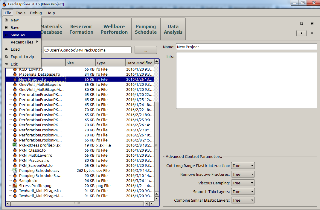
Figure 1: Save a project
or exported to a zip file (Figure 2).
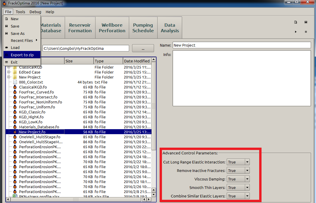
Figure 2: Export a project
The exported file is a zip file, which contains a csv [1] file and a folder after a unzip (Figure 3). The csv file records the Advanced Control Parameters (the red box in Figure 2); while the folder contains all the inputs in specific tabs, for example “Material Database”, “Reservoir Formation”, etc. Thus, the inputs of the specific input tabs can be seen clearly.
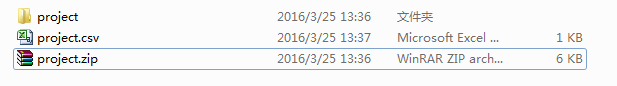
Figure 3: The exported project file
If there are multiple input tables in a single tab, for example there are a number of input sub-tabs in the “Reservoir Formation” tab. One of the input tab data, for example the “Toughness” inputs will be exported as a csv file with the same input sub-tab name “toughness” in the folder “reservoir” (“Reservoir Formation”), which is in the “project folder” after unzipping the exported zip project file (Figure 4).
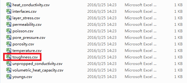
Figure 4: The exported toughness data file in the ”... \(\backslash\) project \(\backslash\) reservoir” folder
The project file can also be saved as a fo (FrackOptima) file, which can be easily loaded (imported) by double clicking it. For example, the current project is “New Project”, user can simply double click the “KGD_Classic” to run classic KGD cases. User can determine whether the current project needs saving (Figure 5).
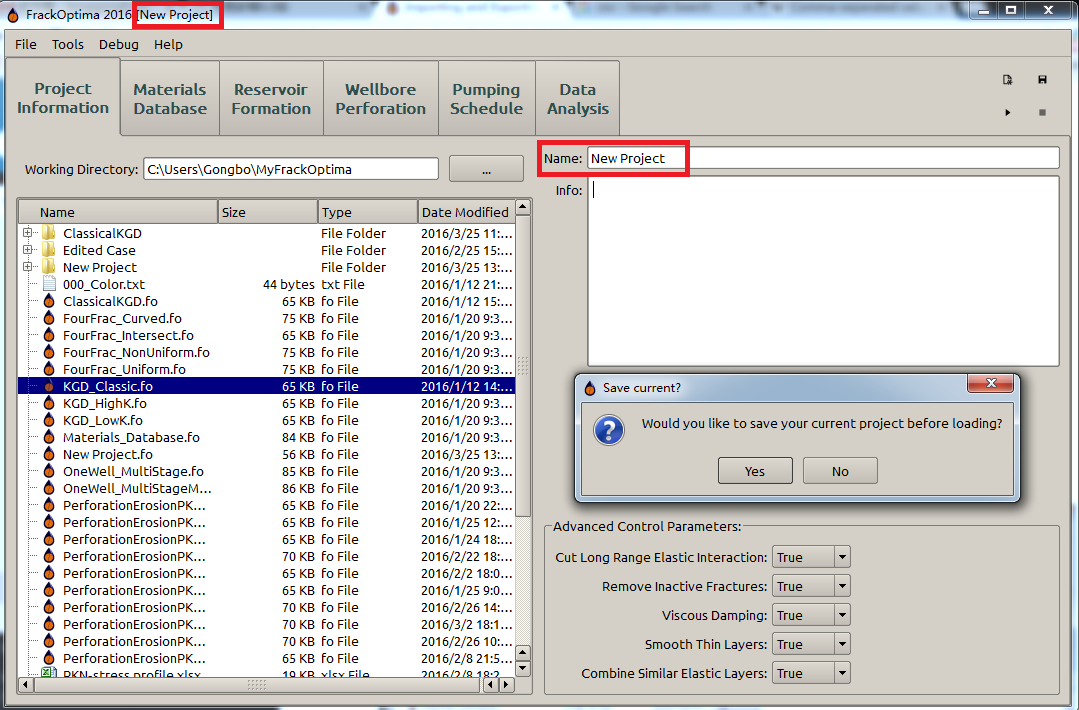
Figure 5: Load (Import) a project file
Individual Tables
A user can export each individual table to a csv file with a user-defined name by clicking the “export” button (the blue box in Figure 6).
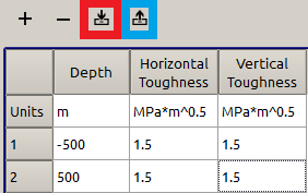
Figure 6: Export and Import button of a table
On the other hand, a user can also import a table from a file by clicking the “import” button (the red box in Figure 6). After that, a popup appears as illustrated in Figure 7, the “Data Manager” is chosen as default.
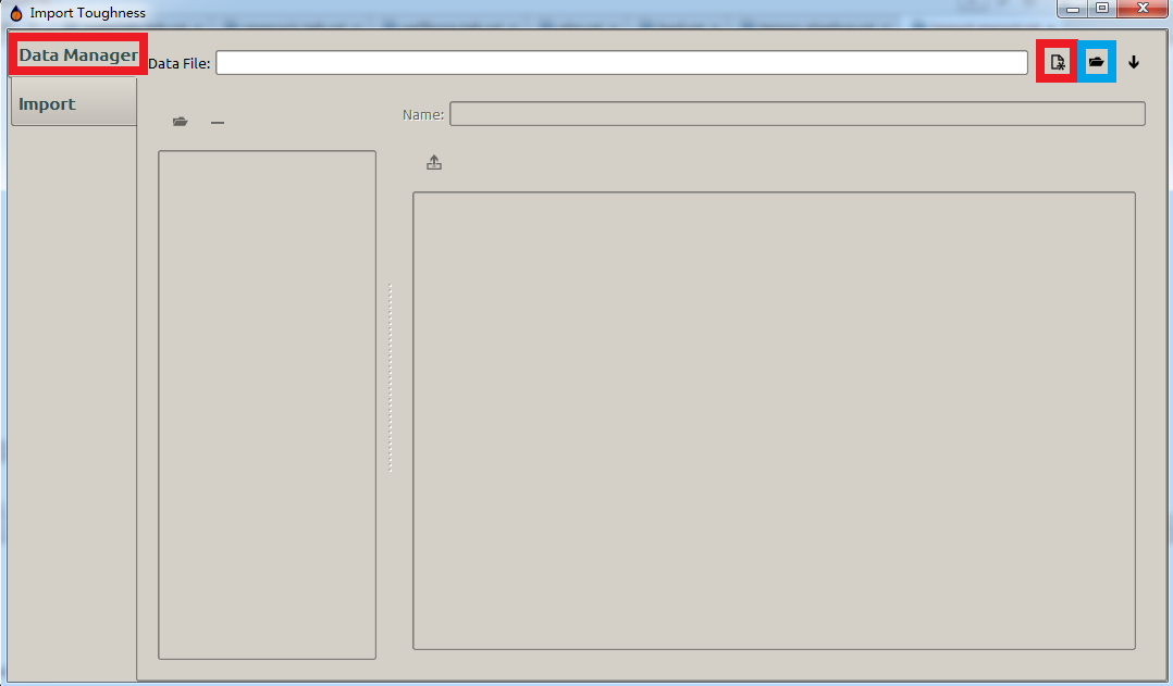
Figure 7: Import a table - Step 1
In Figure 7, there are three active buttons, which represents three ways to carry out the import action. From left to right, the first one (red box in Figure 7) is setting up a new fod, which is the only format FrackOptima can directly import, file to import. The second one (blue box in Figure 7) is importing an existed fod file. The third one (the downward arrow in Figure 7) picks up the most recent fod file to import. The latter two ones are simple because they are direct import actions. Thus, an example is given here for the first option that sets up a new fod file to import.
Having clicked the “new” (red box in Figure 7) button, a user will see a popup as shown in Figure 8
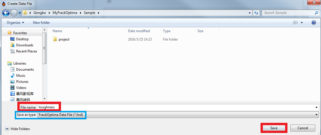
Figure 8: Import a table - Step 2
Then the user can type the file name for the new fod file and save it in the desired folder. After clicking the “save” button, the user will see a sequent popup as shown in Figure 9, which shows the newly established fod file, and then the “Import” button (red box in Figure 9) becomes active to import data from a tabular file (csv, excel, etc.) into the new fod file.
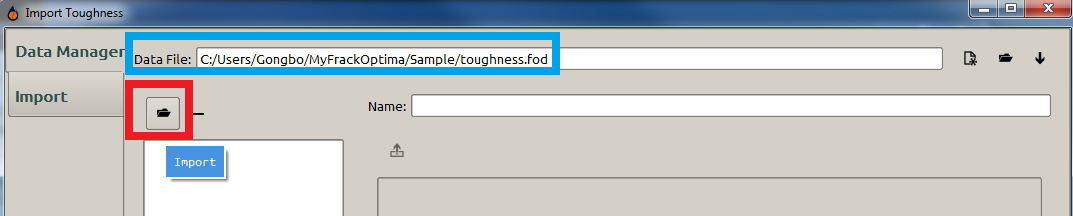
Figure 9: Import a table - Step 3
Once clicking the “Import” button(red box in Figure 9), the user will see the new popup as shown in Figure 10, in which the user can choose a tabular file to import data to the new fod one by clicking the “Browse” button. If there are multiple sheets in the target tabular file, the user may specify which sheet is going to be imported.
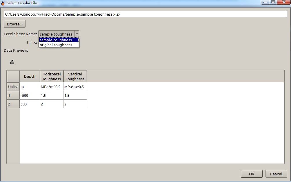
Figure 10: Import a table - Step 4
In addition, the user should specify the unit, usually, by choosing the “Headers” (Figure 11).
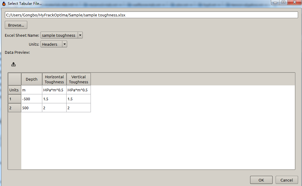
Figure 11: Import a table - Step 5
Then, it goes back to the original “import” popup (Figure 12) if the user clicks “OK” button in Figure 11. In Figure 12, the user can see the data that is going to be imported, and the name of the tabular file (sample toughness in this example) which the data is from.
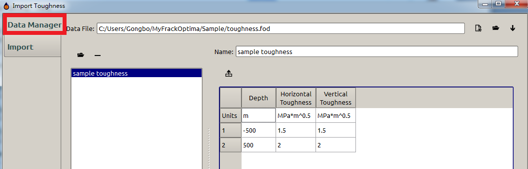
Figure 12: Import a table - Step 6
After that, the user should choose the “Import” tab and click the “Accept” button to complete the import action (Figure 13).
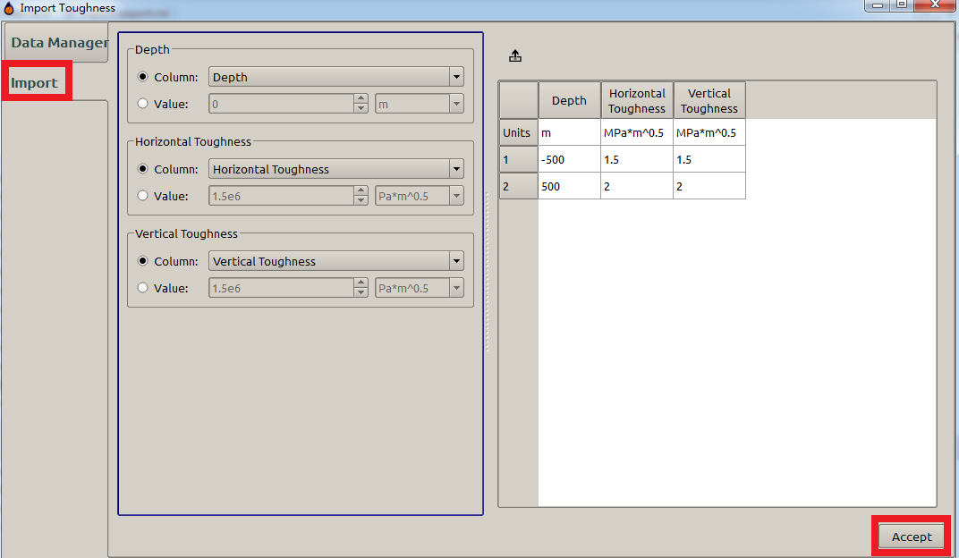
Figure 13: Import a table - Step 7
The imported new data is shown in Figure 14 :
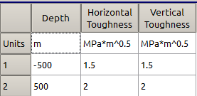
Figure 14: Import a table - Step 8 (Complete)
Warning
For tables that reference materials, like the pumping schedule or interface locations, individual table imports will not accurately import those references. After importing either of those tables, you must input your fluid or proppant columns again.
See also
- Copy and Paste
- For information on how to copy and paste in tables.
Individual Sub-tabs
In “Material Database” tab, there are two sub-tabs “Fluid” and “Proppant” (Figure 15). A user can import specific fluids or proppants from other project file (fo format). Here we take the “Fluid” sub-tab as an example.
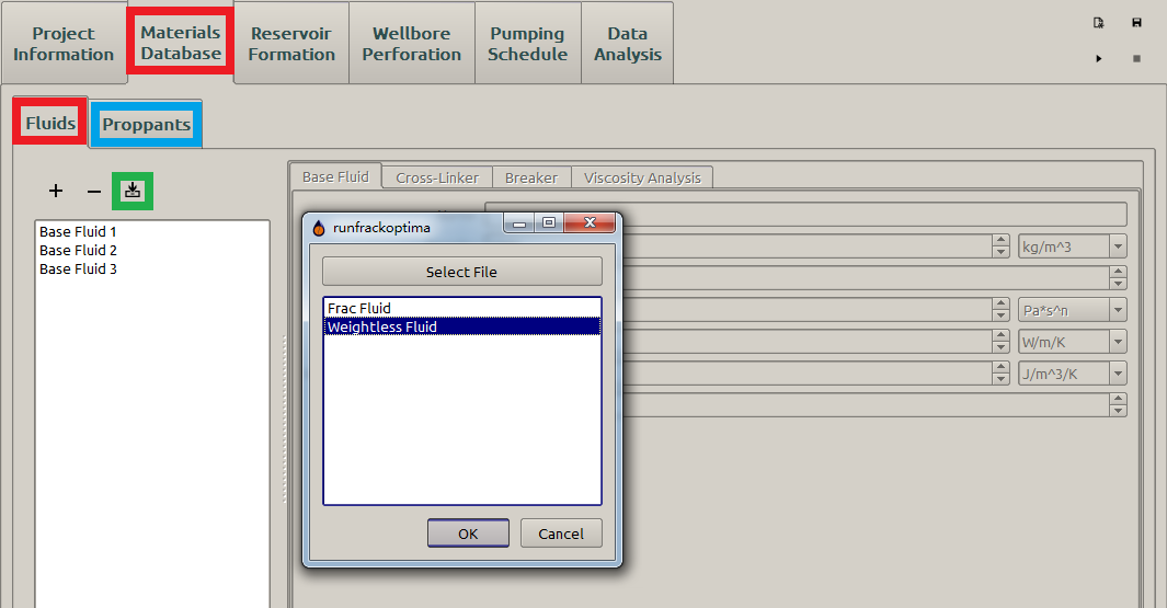
Figure 15: Select a fluid to import
The user wants to import the “Weightless Fluid” defined in “NewProject.fo” file to the current project. He/she clicks the “import” button (green box in Figure 15), clicks the “Select File” button in the popup , and then choose the “NewProject.fo” file (Figure 16) .
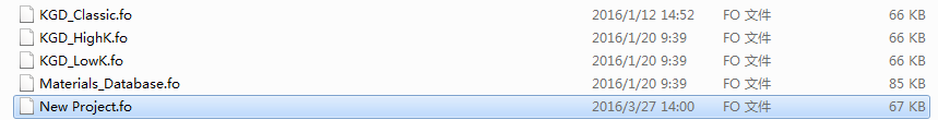
Figure 16: Select the fo file
After that all the fluids defined in the “NewProject.fo” file appears in the popup (Figure 15). The user can pick up the target fluids to import and clicks “OK” to complete the import. Then the new fluid is added (Figure 17).
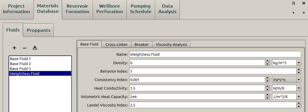
Figure 17: Import the fluid-complete
The user can do the same thing for the “proppant”.
Result Data
FrackOptima has an export feature that allows the user to store all raw result data and plots to a folder. To use it, make sure your project has some result data by running the simulator at least once. Then, go to the “Data Analysis” tab, and click the “Export” toolbox. In that toolbox is an “Export” button. Click that button, and select your export directory in the popup window. Then result data will be saved as a zip file, which yields 2 csv files and a folder called “PerFracData” containing all the specific result parameters after unzip (Figure 18).
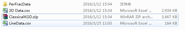
Figure 18: Exported result files
Individual Plots
For the plots in Data Analysis and the Pumping Schedule, right click to bring up a context menu and select Export.... The plots in Wellbore Perforation and Reservoir Formation can be exported by selecting Plot Properties in the respective tab, and pressing the Export Plots... button.