Limited Entry Technique
Introduction
The limited entry technique (LET) is a technology for efficient simultaneous hydraulic fracturing treatment of multiple zones in a low-permeable reservoir (Figure 1).
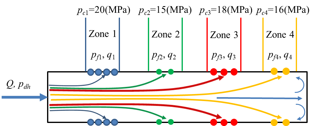
Figure 1: Schematic view of a simultaneous treatment with four injection locations
where:
- \(Q\) is the total volumetric injection rate
- \(p_{dh}\) is the bottom hole treating pressure in a wellbore
- \(p_f\) is the fluid pressure immediate outside a injection location and inside a fracture. It is also called fracture propagation pressure, which is the driving force of the hydraulic fracture
- \(p_c\) is the fracture closure pressure of a zone. It is the resistance of the hydraulic fracture. Only when \(p_f\geq p_c\) can a hydraulic fracture be initiated and propagate
- \(q\) is the fluid injection rate to a perforation
- the subscript index from \(\textrm{1}\) to \(\textrm{4}\) indicates which injection location the pressure and fluid rate are associated with
All the units of the parameters in this document are S.I., unless specified.
Usually, the fluid distribution in different zones is desired to be uniform or controlled to some extents. However, in a hydraulic fracturing treatment with constant \(Q\) , the zone with the least \(p_c\) tends to take most of the treatment fluid, because it requires the least fracture propagation pressure \(p_f\), until some treatment methods are used to divert the fluid. The LET, which controls the treatment fluid distribution (diversion) among different zones by mitigating the impact of variable inter-zonal fracture propagation pressure [1], is one of the fluid-diversion treatment methods. Compared to some conventional treatment methods, the LET is cost-effective and easy to implemented [2].
Conventional Treatment Methods
Before the initial implementation of LET in the early 1960s [2], some other methods known as the “conventional treatment methods” are adopted to divert the fluid, for example the bridge plug and packer arrangement, and ball sealer method (Figure 2).
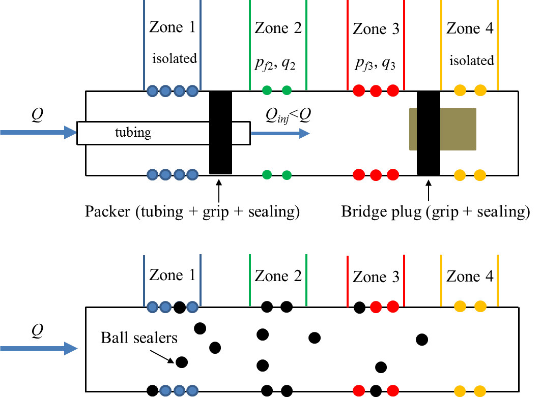
Figure 2: Schematic view of conventional methods for a simultaneous treatment
The bridge plug and packer arrangement (left one of Figure 2) is an effective method that is still used by some oil-service companies currently. It achieves the fluid diversion by placing a series of packer (consisting of tubing, gripping elements and sealing element) and bridge plug (similar to packers but without the tubing) in the wellbore in an appropriate arrangement so that the fluid goes to the targeted zones, while other zones are isolated from being treated. However, this method requires sophisticated well-setting tools to set the packer and bridge plugs (see a sample-video), making it relatively expensive. In addition, the injection rate is considerably reduced , and it is sometimes mechanically hazardous when the bridge plug and packers are set and unset during a treatment [2]. The temporary plugging agent that can be dissolved after some time during a treatment is an alternative for the bridge plug and packer arrangement. However, it is quite difficult to determine the proper quantity to divert the fluid as desired [2].
Unlike the plugging method above to isolate the whole part of the wellbore and the undesired zones, the ball sealers are used to seal the perforations directly. However, it is often ineffective, because some of the sealers fail to seat on the perforations to be isolated, and the abrasion of the sealers seating on those perforations allows fluid by-pass [2].
Therefore, the limited entry technique was developed in the early 1960s to implement the fluid diversion during a treatment in a cost-effective and easily controlled manner.
Limited Entry Technique
Basic Theory
The pressure and injected fluid distribution during a hydraulic fracturing treatment along a horizontal well is illustrated schematically in Figure 3.
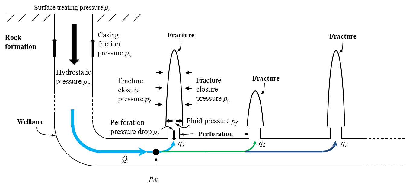
Figure 3: Schematic view of the pressure and fluid distribution during a hydraulic fracturing treatment
The pressure components satisfy the equations:
where, the subscript index \(i = 1,2,3\) ...
And
In Eq (2), \(p_{dh}\) is assumed to remain the same along different injection locations, since the pressure drop due to wellbore friction at different injections is insignificant compared to the perforation pressure drop \(p_r\).
Appropriate design of treatment pressure and fluid distribution obviously requires accurate calculation of various above pressure components, among which the perforation pressure drop (or perforation friction pressure) \(p_r\) turns out to be one of the key unknowns [3].
The Bernoulli equation, as well as the mass conservation equation, is generally adopted by the petroleum industry to estimate the perforation pressure drop \(p_r\) by assuming the fluid is uniformly distributed among perforations at one injection location [4] [5]:
where:
- \(\rho\) is the density of the treatment fluid
- \(n_i\) is the number of perforations at the \(i\) th injection location
- \(C_d\) is the dimensionless discharge coefficient, which is a kinetic energy correction factor for the fluid flow and represents the effect of the perforation entrance shape on the pressure drop [6] [7] [8], at the \(i\) th injection
- \(D\) is the perforation diameter at the \(i\) th injection
- \(D_w\) is the wellbore diameter
- \(m\) is the total number of the injection locations
The second term of the first equation of Eq. (3) is usually neglected because \(D_w\) is significantly larger than \(D\) , and \(n_i\) is limited in LET.
From Eq. (3), at one injection location, when the number of perforations \(n_i\) is limited (decreasing), the perforation pressure drop \(p_{ri}\) increases. During a fracturing treatment, this increased \(p_{ri}\) through these limited entries (perforations) plays the role of so-called backpressure which create an increase in bottom-hole treating pressure \(p_{dh}\), while the total injection rate \(Q\) remains constant. In other words, the perforations are acting as individual bottom-hole chokes to increase \(p_{dh}\) [2] .
When the different fracture closure pressure \(p_{ci}\) requires variable \(p_{fi}\) to overcome, the increased \(p_{dh}\) makes \(p_{ri}\) (Eq. (3)) at different zones differ less from each other. In other words, the pressure difference of inside wellbore (\(p_{dh}\)) and outside wellbore (\(p_{fi}\)) gets mitigated for different zones (injection locations). Thus, the fluid can be distributed more uniformly or be controlled to a better extent.
Example
Assume the bottomhole treating pressure \(p_{dh}=20.5(\textrm{MPa})\), and the fracture propagation pressure \(p_{fi}=p_{ci}\) in each zone as in Figure 1. Then the perforation pressure drop at Injection \(1\) and \(2\) are:
The \(p_{r2}\) is \(11\) times of \(p_{r1}\), making the fluid distribution among these two injections differ a lot. Then the LET is implemented by decreasing either the number of perforations \(n_2\) or the perforation diameter \(D_2\) at the Injection \(2\), so that \(p_{r2}\) increases to about \(7(\textrm{MPa})\). As a result:
\[\begin{split}\left\{ \begin{align} & p_{dh} = p_{c2} + p_{f2} = 7+15 = 22(\textrm{MPa}) \\ & p_{r1} = p_{dh} - p_{f1} = 22-20 = 2(\textrm{MPa}) \\ \end{align} \right.\end{split}\]
The new \(p_{r2}\) is then \(3.5\) times of the new \(p_{r1}\). The pressure difference inside the wellbore and outside the wellbore in this two zones decreases from \(11\)-fold to \(3.5\)-fold. In other words, the impact of variable inter-zonal fracture propagation pressure is mitigated, and the fluid distribution is controlled to be uniform to some extents by limiting the number of perforations or changing the perforation diameters at appropriate zones. This control manner is easy to carried out and cost-effective compared to the foregoing conventional methods.
Factors that affect the limited entry treatment
The best treatments are obtained by maintaining perforation pressure drop \(p_{ri}\) maximum during a treatment. Because it provides the most mitigation of the impact of variable inter-zonal fracture propagation pressure, so that the most assurance that all zones are treated is achieved. As a consequence, smaller perforation diameter \(D\) is preferred according to Eq. (3). The fourth power of \(D\) ensures the maximum \(p_r\) , while the injection rate does not need to be high and, as a result, less hydraulic surface power is needed. For practical treatments, \(\frac{3}{8}\) inch diametric perforations are generally used.
Because the perforation diameter \(D\) plays such an important role for the LET, a change on it will affect the perforation pressure drop \(p_r\) significantly and the whole treatment consequently. When the proppant is added, it erodes perforations and then enlarge \(D\), resulting in a decrease in \(p_r\) to some extent. In addition, the increased \(D\) and the perforation smoothing due to the erosion also enlarged \(C_d\), making \(p_r\) further decrease. Thus, it is critical to model the change of \(D\) and \(C_d\) during a limited entry treatment and that is why FrackOptima developed our own perforation model [9] to model the change of these two parameters and the subsequent issues, for example the fluid redistribution. If the LET is not considered, i.e. an adequate number of suitable size perforations is available, the \(p_r\) is usually assumed zero [7].
LET can also be designed so that the desired amount of fluids is injected into each zone. This is an important advantage where thick zones, which require more treatment, are treated in conjunction with thin zones. If the fracture closure pressure \(p_c\) in different zones are similar, each zone will be given the desired amount of treatment fluid by proportioning the number of perforations according to the thickness of the zone.
However, if considerable variations exist in the \(p_c\) of different zones, the treatment design should be different. The zone with lowest \(p_c\) normally receives the most treatment per perforation [1]. Thus, the number and/or size of the perforations should be reduced in this zone (see the example). The converse holds true for the zone with the highest \(p_c\).
Reference
| [1] | (1, 2) Cramer. Perforating for Controlled Hydraulic Fracturing. A presentation made in 2010 |
| [2] | (1, 2, 3, 4, 5, 6) Lagrone and Rasmussen. A New Development in Completion Methods-The Limited Entry Technique. Journal of Petroleum Engineers. 15 (07). 1963 |
| [3] | Willingham, Tan, and Norman. Perforation Friction Pressure of Fracturing Fluid Slurries. Presented at the SPE Low Permeability Reservoirs Symposium, Denver, 26-28 April 1993. SPE-25891-MS. |
| [4] | Cramer. The Application of Limited-Entry Techniques in Massive Hydraulic Fracturing Treatments. Presented at the SPE Production Operations Symposium, Oklahoma City, 8-10 March 1987. SPE-16189-MS. |
| [5] | Crump and Conway. Effects of Perforation-Entry Friction on Bottomhole Treating Analysis. Journal of Petroleum Technology. 40 (08); 1041-1048. 1988 (Lord et al. 1994; Romero et al. 1995; El-Rabba et al. 1999) |
| [6] | Lord, Shah, Rein and Lawson. Study of Perforation Friction Pressure Employing a Large-Scale Fracturing Flow Simulator. Presented at the SPE Annual Technical Conference and Exhibition, New Orleans, 25-28 September 1994. SPE-28508-MS. |
| [7] | (1, 2) Romero, Mack, and Elbel. Theoretical Model and Numerical Investigation of Near-Wellbore Effects in Hydraulic Fracturing. Presented at the SPE Annual Technical Conference and Exhibition, Dallas, 22-25 October 1995. SPE-30506-MS. |
| [8] | El-Rabba, Shah, and Lord. New Perforation Pressure-Loss Correlations for Limited-Entry Fracturing Treatments. SPE Prod & Fac. 14 (01) 1999. 63-71. |
| [9] | Long, Liu, Xu, and Wong. Modeling of Perforation Erosion for Hydraulic Fracturing Applications. Presented at the SPE Annual Technical Conference and Exhibition, Houston, 28-30 September 2015. SPE-174959-MS. |